

PG4UW
Common control program for Windows for all Elnec programmers.
A 32-bit application works with:
Windows XP operating system (32-bit and 64-bit)
Windows Server 2003 operating system
Windows Vista operating system (32-bit and 64-bit)
Windows 7 operating system (32-bit and 64-bit)
Windows 8 operating system (32-bit and 64-bit)
Windows 8.1 operating system (32-bit and 64-bit)
Windows 10 operating system (32-bit and 64-bit)
Windows 11 operating system (64-bit)
with pull-down menus, hot keys and online help.
Software features:
- standard operations with buffer and device
- security features
- insertion test, Signature-byte check
- special features
- serialization, complex statistics, automatic YES!, remote control, JTAG daisy chain, etc.
- complex device information available
- device package dimensions / ISP connection info, part numbering info,detailed notes for more complicated devices, etc.
- supported all well-know data formats
- multilanguage interface
- 9 different language variations (English, Korean, Chinese, Japanese, German, French, Russian, Portuguese, Slovak)
- only manufacturer approved or certified algorithms used
- Windows and online help
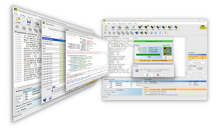
Software description
Control program PG4UW is a 32-bit application for MS Windows (from Windows XP to Windows 11, 32-bit and 64-bit) with pull-down menu, hot keys and online help. You can select target device by its class, by manufacturer or simply by typing a fragment of vendor name and/or a part number. Besides the standard device-related commands (read, blank check, program, verify, erase) have been implemented some test functions (insertion test, signature-byte check), and some special functions (autoincrement, projects, production mode - start immediately after insertion of chip into socket). The control program permits data manipulation within the buffer and between the buffer and files and performs automatic file format detection and conversion. The software is available in english and in more another languages.
Easy to use interface
- intuitive icons and simple menu allows you easily work with program
- toolbars could be visible or hidden
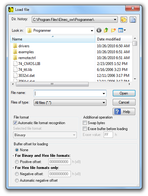
- files are easily selectable from standard open (or save) file dialog
- Automatic file format recognition make easy the input file handling. SW accept mostly all available file formats - Binary (RAW), Intel (Extended) HEX, MOTOROLA, MOS Technology, Tektronix, ASCII space, JEDEC and POF
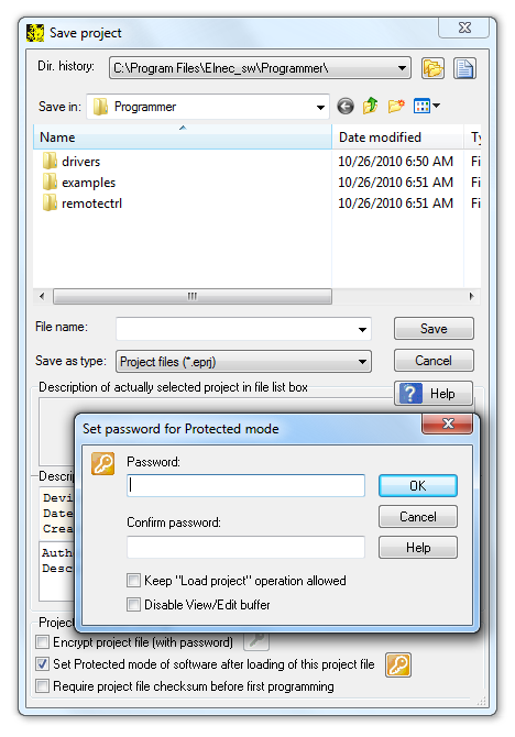
- once configured, the device settings can be stored into project (also known as job)
- project protection settings help elmiminate human factor faults, espacially in mass production
General options
File options
File options page allows you to set file masks, auto-reload of current file and choose file format recognizing for loaded files. When you select Auto-reload in part When current file is modified by another process debugging your application is so easy. Load your file to control program PG4UW and open it in any other text editor together. Try programmed device in your applications. When the device doesn't work correctly, modify the file in the text editor (and save it), then switch to PG4UW. PG4UW automatically reloads this file and you may program your device again.
Language
This page allows you to select another language for user interface such as menu, buttons, dialogs, information and messages. It also allows to select wished help file in another language. For another language support of user interface the language definition file is required (contact your distributor).
Sound
Sound page allows user to select the sound mode of program. Program generates sounds after some activities, e.g. activities on device (programming, verifying, reading, etc.) and when warning or error message is displayed also. User can now select sound from MS Windows system sound (required installed sound card), PC speaker, programmer speaker (JetProg) or none sound.
Standard operations
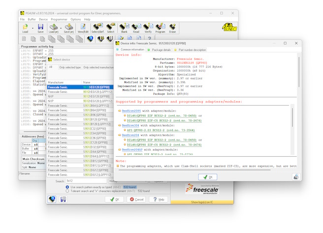
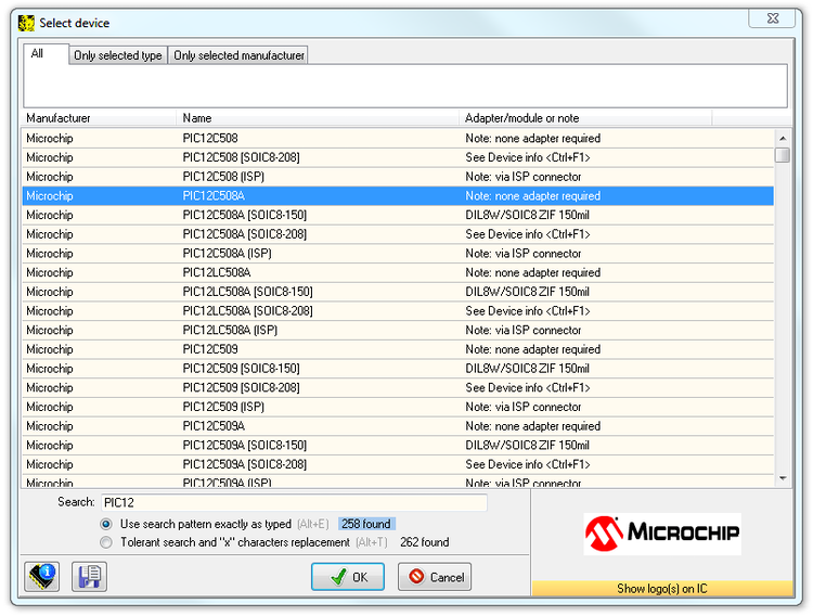
Select device
You can select target device by its class, by manufacturer or simply by typing a fragment of vendor name and/or part number.
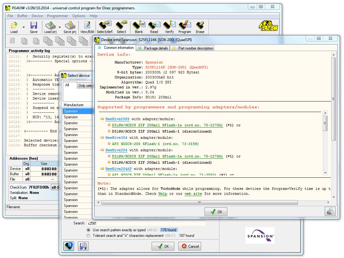
Device info
- additional information about selected device may be displayed by pressing <Ctrl + F1> or Device info button.
- the drawing of all available packages are provided.
- software provide also explanation of chip labelling (the meaning of prefixes and suffixes at the chips) for each supported chip.
- software provides a full information for ISP implementation: Description of ISP connector pins for currently selected chip, recommended target design around in-circuit programmed chip and other necessary information.
Select EPROM/Flash by ID
Use this command to autoselect an EPROM or Flash as active device by reading the device ID. The programmer can automatically identify certain devices by the reading the manufacturer and the device-ID that are burnt into the chip. This applies to EPROM or Flash that supports this feature only. If the device does not support a chip ID and manufacturer's ID, a message will be displayed indicating this as an unknown or not supported device.
Warning:
We don't recommend apply this command to 2764 and 27128 EPROM types, because most of them doesn't supports ID.
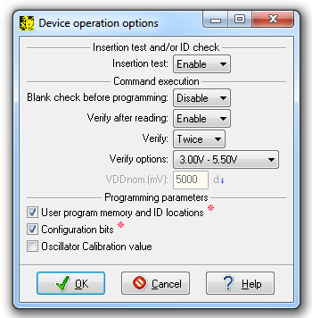
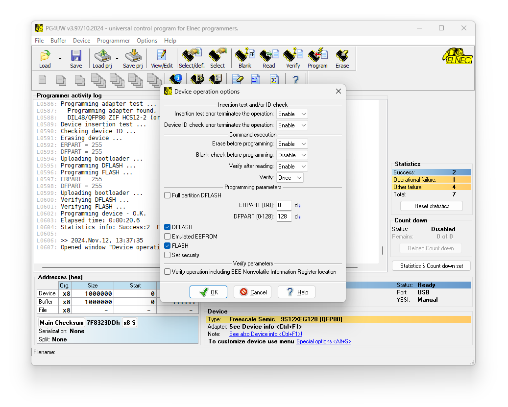
Device operation options
All settings of this command are used for programming process control. This is a flexible environment which contains items associated with current device and programmer type.
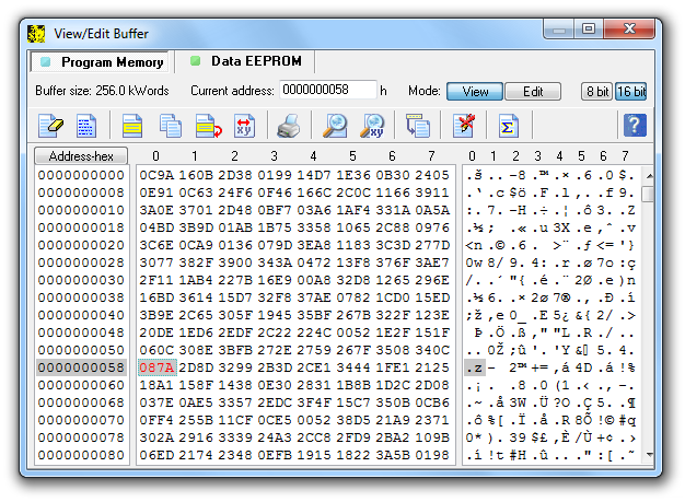
View/Edit buffer
This window is used for buffer manipulation, block operation, filling a part of buffer with string, erasing, checksum and of course editing and viewing with other items (find and replace string, printing...).
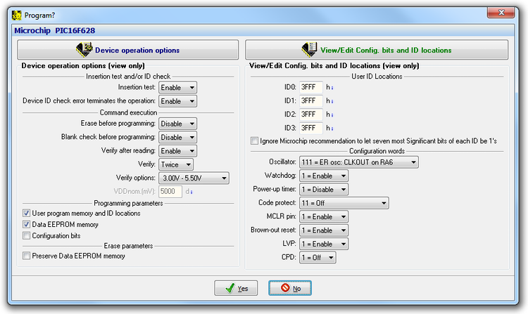
Program
This command allows programming the whole device or its part by the data of the buffer. The control program reports a result of this action to Log window. Information about device operation options and optional settings are displayed in window below. Pressing button Device operation options (or Alt + O) you could change Device operation options. Pressing button on the top of right panel (or Alt + S) you could change optional settings.
Security features
Insertion test
Some of the programmers perform device insertion test (wrong or backward position) and contact check (poor contact pin-to-socket) before action with the device.
Signature-byte check
Some of the programmers perform signature-byte check before action with most of devices. The programmer can automatically identify certain devices by reading the manufacturer and the device-ID that are burnt into the chip.
These capabilities supported by overcurrent protection helps to prevent chip damage due to operator error.
Special features
Serialization
Serialization is a special mode of the program. When a serialization mode is activated a specified value is automatically inserted on predefined address into the buffer before programming each device. When more devices are programmed one by one, the serial number value is changed for each device automatically and inserted into the buffer before programming the device so each device has the unique serial number.
There are three types of serialization:
- Incremental mode and SQTP
- From-file mode
- Custom generator mode
Incremental mode and SQTP
The Incremental mode & SQTP enables to assign individual serial numbers to each programmed device. A starting number entered by user will be incremented by specified step for each device program operation and loaded in selected format to specified buffer address prior to programming of each device. Options available in Incremental mode serialization allow also set equivalent serialization to Microchip SQTP used for Microchip PICmicro® devices
From-file mode
Using the From-file method, serial values are read from the user specified input file(s) and written serialization data to buffer on specified addresses.
Custom generator mode
Custom generator serialization mode provide maximum flexible serialization mode, because the user have serialization system fully in his hands. When Custom generator mode of serialization is selected, serial numbers are generated by user made program “on-the-fly” before each device is programmed in PG4UW or PG4UWMC. Custom generator mode serialization allows user to generate unique sequence of serial numbers desired. Serial numbers can be incremented as a linear sequence or completely non-linear sequence. The user made serial number generator program details are described later in the following section Custom generator program.
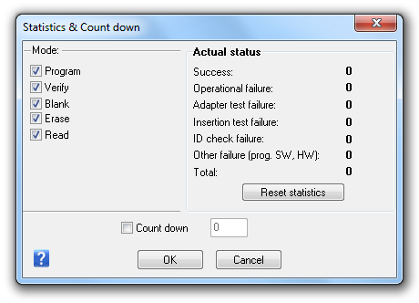
Statistics
Statistics gives the information about actual count of device operations which were proceeded on selected type device. If one device is corresponding to one device operation, e.g. programming, the number of device operations will be equal to number of programmed devices. The next function of statistics is Count down. Count down allows checking the number of device operations and then number of devices on which device operations have to be done.
Automatic YES!
This command is used for setting Automatic YES! mode. In this mode you just put a device into ZIF socket and a last operation will be repeated automatically. Program automatically detects an insertion of a new device and runs last executed operation without pressing any key or button. This feature is not supported by some programmers.
Project, Protected project
Project contains device configurations (name and manufacturer of selected device, device operation options of this device), data of buffer, user interface configuration, description of project, author and date of project creation. Protected project - this feature allows to eliminate operation errors, because operator haven't (or can not) modify any parameters of programming. It's so easy: load project and then only insert devices into ZIF socket.
Remote control support of PG4UW software
The remote control feature allows to be PG4UW software flow controlled by other application – either using .BAT file commands or using DLL file. Remote control of PG4UW control program allows to control selected functions of PG4UW application by other application. This is very suitable feature for integrating Elnec programmer into ATE machines for on-board IC programming and for on-board manual programming (using bed-of-nails) - to control PG4UW from the integrated development environment software.
Two basic ways to remote control of PG4UW:
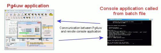
Pict. 1: Controlling PG4UW with remote control program (example: program PG4UWrem.exe - part of PG4UW software delivery).
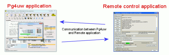
Pict. 2: Controlling PG4UW with command line remote control program PG4UWcmd.exe (also part of PG4UW software delivery).
For further information about remote control of PG4UW, please look at PG4UW remote control manual (inside of software installation package).
Important:
- the remote control over DLL file is not available for 40-pindrive programmers (e.g. SmartProg2).
- Remote control of PG4UW can be used also for multiprogramming, but this feature is available only of on-board programmed devices (programming using ISP connector)
- for off-board multiprogramming (like implementation of programmer into automated programming machine), it is available PG4UWMC remote control system
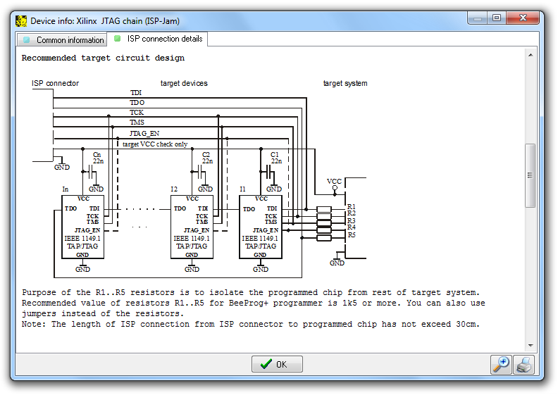
JTAG daisy chain
Connecting multiple devices via their JTAG ports is commonly referred to as JTAG daisy chaining. PG4UW software supports programming and testing multiple devices via their JTAG ports in JTAG daisy chaining.
The pins TMS and TCK are connecting directly, but the pin TDO from one device goes to the pin TDI of next device. When using a JTAG chain with mixed voltage devices, extra care must be taken to ensure the integrity between the devices. The devices in JTAG chain can be programmed and tested. It is possible to choose JTAG chain (ISP-Jam) for Altera and Xilinx devices or JTAG chain (ISP-VME) for Lattice devices.
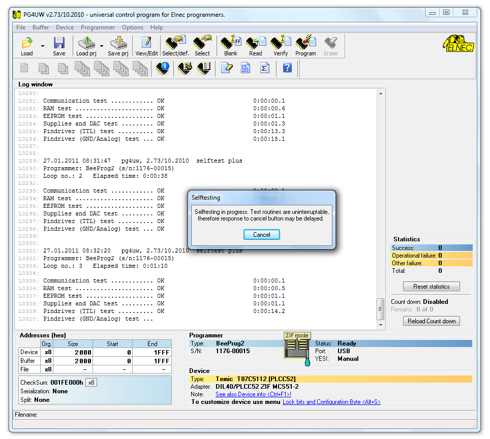
Diagnostics
These routines execute selftest with or without diagnostic POD of current programmer (not supported by some programmers). We recommend run these routines as often as possible, e.g. once per month.
Supported programmers by PG4UW software
- BeeHive304
- BeeProg3
- BeeHive208S
- BeeHive204
- BeeHive204AP
- BeeHive204AP-AU (discontinued)
- BeeProg2
- BeeProg2AP
- BeeProg2C
- SmartProg2
- MEMprog2 (discontinued)
- BeeProg+ (discontinued)
PC System requirements
- Requirements to the PC and operating system are changed time to time as a result of increased number of supported device, added new features of the software and when new device programmer is integrated into software.
- List of all actual requirements to the PC and operating system.
* Windows is a registered trademark of Microsoft Corporation in the United States and other countries.
