

|
|
| Ord. no. | 73-4360 |
|---|---|
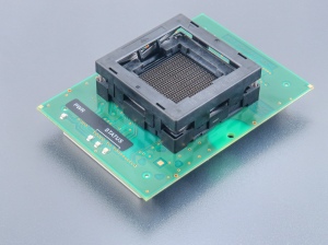
| Socket | ZIF BGA484, OpenTop type |
| Bottom | 2 connectors by 68 pins, receptacle type |
| Class | Specialized |
| Subclass | NEC MCU |
| Availability in stock |
0 pcs.
[ We are sorry, that the item is not in stock at the moment. Please ask for availability, click here. other 4 pcs. within 4 working days ]
This number indicates quantity of items that could be produced from components in stock. Reasonable quantity of this product can be available within 4 working days. |
Module manual
- Programmer don"t need to be switched off and SW can be running during inserting/removing programming module
- Protect the contacts of module connectors and ZIF socket from contamination. Any dirt and/or fat on contacts may cause errors during programming.
- Proceed with care! Incorrect insertion of device in module ZIF socket may lead to programmed device damage.
- Unscrew 2 knurled thumb screws. Insert programming module into Programming Module Interface connectors, until it clicks. Due to connectors shape, only one orientation and position of programming module in Programming Module Interface connectors is possible. Screw 2 knurled thumb screws to fix programming module to programmer.
- Push the cover of module ZIF socket (the topmost movable part) to open the socket. Once fully actuated, drop the device into the socket from a height of 2 to 3mm above the seating plane. The correct position of the programmed device is shown on PCB of the module. The reference corner (position of pin A1) of the device is indicated by dot. Then release module ZIF socket.
- The cover must be fully actuated (depressed) before inserting a device into the socket.
- Do not press on device while inserting it and/or releasing the cover.
- Visually check the placement of programmed device in module ZIF socket. If everything looks OK, the device is ready for programming.
- To take out the device from module, push the cover of module ZIF socket and remove the device.
- When you finish the work with module, unscrew 2 knurled thumb screws and remove the module from Programming Module Interface connectors.
- Operating conditions: temperature 5°C ÷ 40°C (41°F ÷ 104°F), humidity 20% ÷ 80% non-condensing
- Check brochure - https://www.elnec.com/sw/3m_tweezer_handling.pdf - for details on proper insertion procedure of chip/device into this ZIF socket.
Software note
- If software version, you're using currently, doesn't contain support for this programming module, please download the latest version of software - Regular or OnDemand - from our web site.
Accepted package(s)
| BGA package |
 |
 |
| NAME | SYMBOL | MIN | NOM | MAX |
| Profile | A | 1.63 | 1.83 | 2.03 |
| Ball Height | A1 | 0.4 | 0.5 | 0.6 |
| Body Thickness | A2 | - | 1.33 | - |
| Ball Diameter | b | 0.5 | 0.6 | 0.7 |
| Body Size | D | 22.9 | 23 | 23.1 |
| Body Size | E | 22.9 | 23 | 23.1 |
| Ball Pitch | e | - | 1 | - |
| Ball Array D | GD | - | 22 | - |
| Ball Array E | GE | - | 22 | - |
