Discontinued product! Please go to discontinued products section to find the replacement.
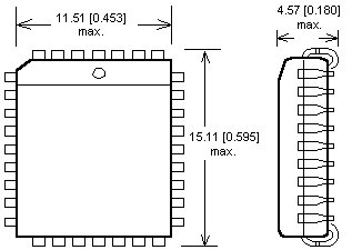
Table with adapter specifications
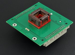
specialized programming module for NOR Flash devices in PLCC32 package
operating (mechanical) warranty of ZIF socket – 10,000 actuations (We"re sorry, but we"re not able to provide warranty of reliable contact over the mechanical lifetime of ZIF socket - please read note below)
NOTE: This programming module was manufactured on the pressure of some customer, but we don`t recommend to use it for programming. Reason: the quality of this PLCC ZIF socket is not sufficient for manufacturing purposes, but this model of ZIF socket is only one open-top type of PLCC we know (exist on the market). For programming of devices in PLCC packages, we recommend to use manual programming and programming adapters with ClamShell type of ZIF socket.
Programmer don`t need to be switched off and SW can be running during inserting/removing programming module
Protect the contacts of module connectors and ZIF socket from contamination. Any dirt and/or fat on contacts may cause errors during programming.
Proceed with care! Incorrect insertion of device in module ZIF socket may lead to programmed device damage.
Unscrew 2 knurled thumb screws. Properly Insert programming module into Programming Module Interface connectors, until it clicks. Due to connectors shape, only one orientation and position of programming module in Programming Module Interface connectors is possible. Screw 2 knurled thumb screws to fix programming module to programmer.
Push the cover of module ZIF socket (the topmost movable part) to open the socket. Insert the device into module ZIF socket. Correct position of programmed device in module ZIF socket is indicated by picture near (usually on left above) the module ZIF socket. On that picture, reference corner of device (e.g. position of pin 1) is indicated by dot, by number 1, by bevelled corner or by any combination of mentioned. Then release module ZIF socket.
The cover must be fully actuated (depressed) before inserting a device into the socket. If device is inserted into only partially opened ZIF socket, then - after releasing of cover – device pins might be damaged.
Pull a lid (the upper - moving - part of ZIF) of programming module a bit up to gain reliable contact.
Visually check the placement of programmed device in module ZIF socket. If everything looks OK, the device is ready for programming.
To take out the device from module, push the cover of module ZIF socket and remove the device.
When you finish the work with module, unscrew 2 knurled thumb screws and remove the module from Programming Module Interface connectors.
If software version, you're using currently, doesn't contain support for this programming module, please download the latest version of software - Regular or OnDemand - from our web site.