will be discontinued, discounted price on current stock
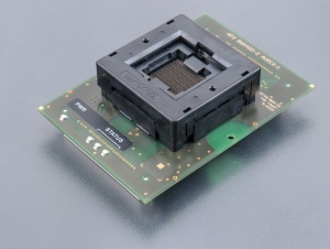
specialized programming module for Infineon SAK-TC23xx-xxxxxxx, SAK-TC27xx-xxxxxxx, SAK-TC29xx-xxxxxxxx devices in LFBGA292 package
used ZIF socket may accept one or more variants of supported package, different in ball diameter, ball high and/or body thickness, see section Accepted package(s)
operating (mechanical) warranty of ZIF socket - 10,000 actuations
Programmer don`t need to be switched off and SW can be running during inserting/removing programming module
Protect the contacts of module connectors and ZIF socket from contamination. Any dirt and/or fat on contacts may cause errors during programming.
Proceed with care! Incorrect insertion of device in module ZIF socket may lead to programmed device damage.
Unscrew knurled thumb screw. Insert programming module into Programming Module Interface connectors, until it clicks. Due to connectors shape, only one orientation and position of programming module in Programming Module Interface connectors is possible. Screw knurled thumb screw to fix programming module to programmer.
Push the cover of module ZIF socket (the topmost movable part) to open the socket. Once fully actuated, drop the device into the socket from a height of 2 to 3mm above the seating plane. The correct position of the programmed device is shown on PCB of the module. The reference corner (e.g. position of pin A1) of the device is indicated by dot, by number 1, by bevelled corner or by any combination of mentioned. Then release module ZIF socket.
The cover must be fully actuated (depressed) before inserting a device into the socket.
Do not press on device while inserting it and/or releasing the cover.
If software version, you're using currently, doesn't contain support for this programming module, please download the latest version of software - Regular or OnDemand - from our web site.