Discontinued product! Please go to discontinued products section to find the replacement.
Table with adapter specifications
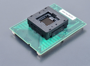
top board of BGA adapters
used ZIF socket may accept one or more variants of supported package, different in ball diameter, ball high and/or body thickness, see section Accepted package(s)
operating (mechanical) warranty of ZIF socket - 10,000 actuations
supported from PG4UW software version 3.22r, s/n from 3803-00162 are supported from PG4UW software version 3.76
Proceed with care! Incorrect insertion of adapter in programmer ZIF socket or device in adapter ZIF socket may lead to programmed device damage.
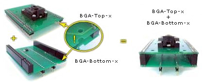
For work with BGA device it is necessary put together BGA-Top-X with some BGA-Bottom-X board according to the information provided by PG4UW software for each particular device (menu Device/ Device info).
The picture shows, how to put together the BGA-Top-X and BGA-Bottom-X board to have complete BGA adapter.
Insert complete adapter into programmer ZIF socket. If you are in doubts about orientation of the adapter in programmer ZIF socket, there is a rule of thumb - orientation of adapter name text is the same as orientation of the text on the top of programmer.
Visually check the placement of adapter in programmer ZIF socket.
Push the cover of adapter ZIF socket (the topmost movable part) to open the socket. Once fully actuated, drop the device into the socket from a height of 2 to 3mm above the seating plane. For correct device orientation, follow the instructions shown on picture in PG4UW software Device info window for device being programmed. Then release adapter ZIF socket.
The cover must be fully actuated (depressed) before inserting a device into the socket.
Do not press on device while inserting it and/or releasing the cover.
If software version, you're using currently, doesn't contain support for this programming module, please download the latest version of software - Regular or OnDemand - from our web site.